Aircraft / 2025
Aurora
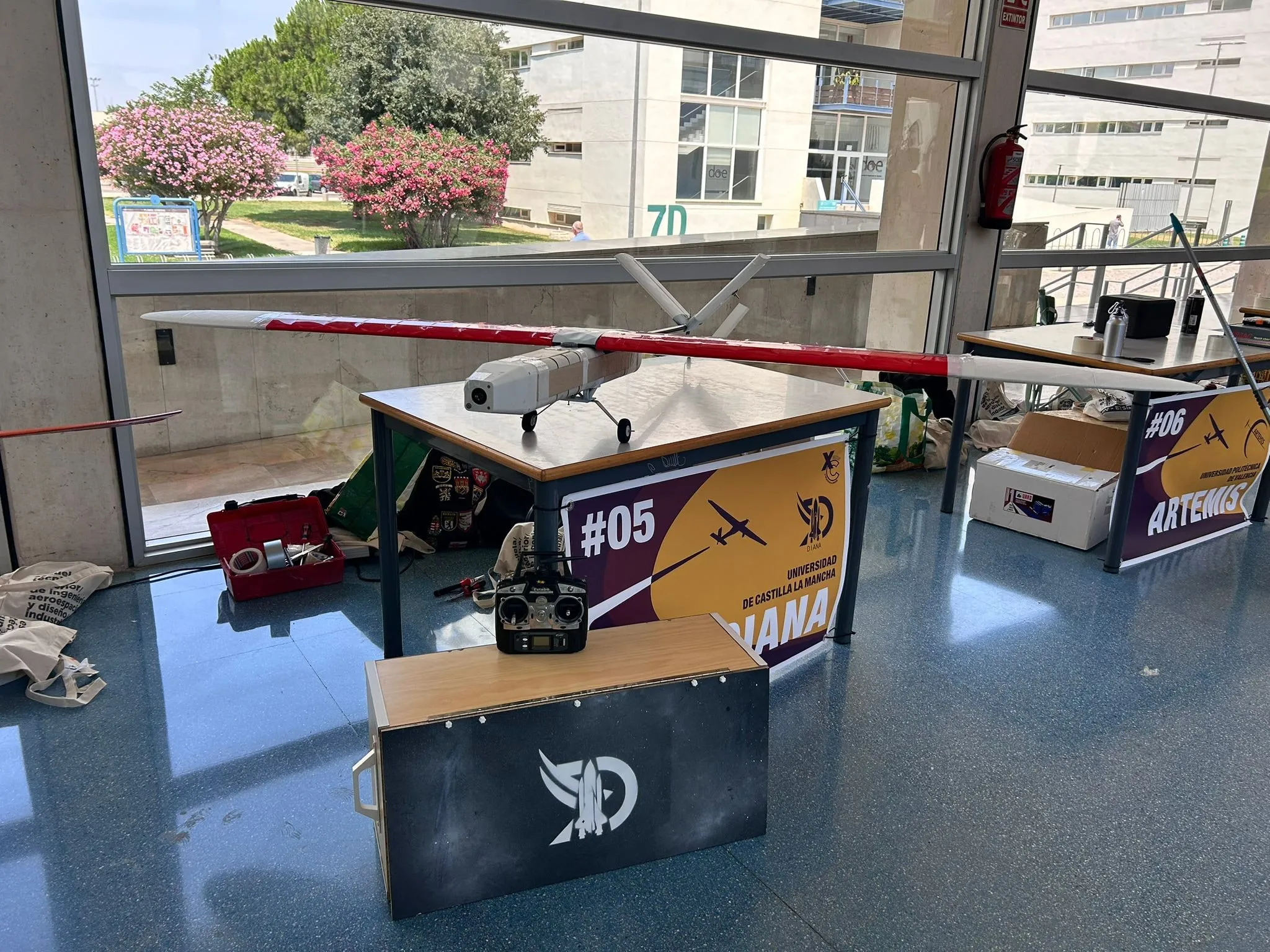
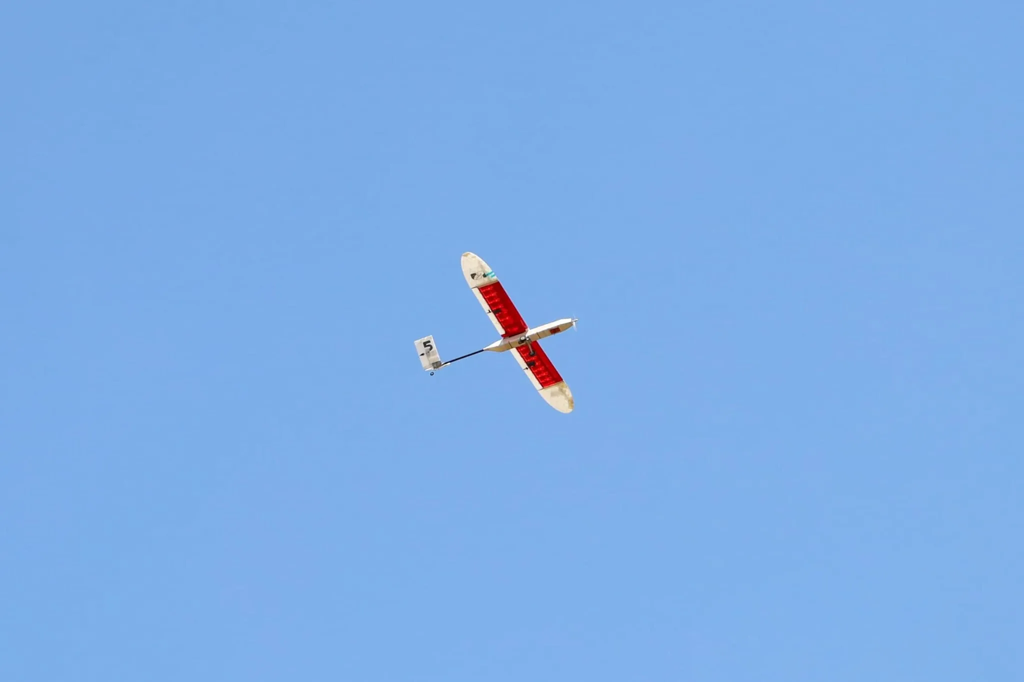
Hybrid balsa and LW-PLA wing with a printed elliptical tip. After eight prototypes crashed, it completed the XtraChallenge 2025 circuit with a borrowed motor.
- Aircraft
- Aurora
- Season
- 2024/25
- Competition
- XtraChallenge 2025
- Result
- 13th of 15 · 2 awards
- Sheet
- 2 / 3
Technical data
Geometry
| Wingspan | 2,500 mm |
|---|---|
| Length | 1,665 mm |
| Wing area | 0.67 m² |
| Root chord | 300 mm |
| Mean aerodynamic chord | About 290 mm, calculated from the wing geometry |
| Aspect ratio | 9.33 |
| Planform | Straight section over 65 % of the span and an elliptical tip |
| Wing aerofoil | Clark YChosen over the E216, S3021 and SD7037 for its greater thickness |
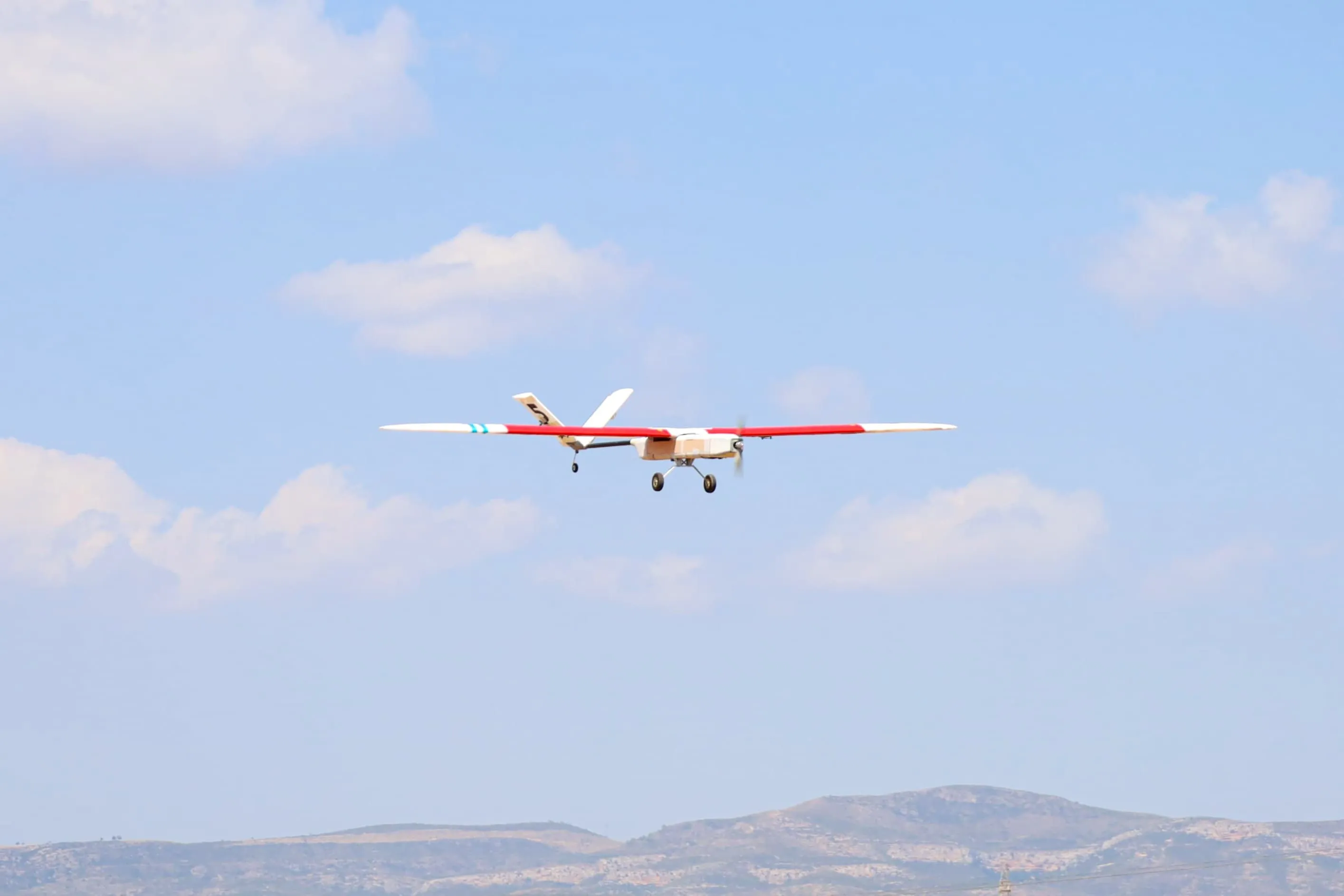
| Tail | V-tail |
| Tail aerofoil | NACA 0010 |
Masses
| Empty mass | 3 kg |
|---|---|
| Maximum payload | 750 ml of water, in internal tanks |
| Maximum take-off mass | 3.75 kg |
Performance
| Stall speed | 8.09 m/s |
|---|---|
| Take-off speed | 10 m/s |
| Cruise speed | 18.5 m/s |
| CL at 0° | 0.216 |
Propulsion
| Motor | Emax GT2820/06 985KV |
|---|---|
| Propeller | APC 10x6E |
| Power battery | Turnigy Graphene Panther 3S, 3,000 mAh, 75C |
| Speed controller | 40 A, budget range |
Avionics
| Transmitter | Futaba T6EX |
|---|---|
| Receiver | Futaba R617FS |
| Flight controller | None, flown with direct control and no electronic stabilisation |
| Flaperon servos | Emax ES3352, 12.4 g, metal gears |
| Tail servos | MG90S, 13 g |
| Receiver battery | Gens Ace 2S, 1,000 mAh |
| 5 V supply | UBEC |
Structure and manufacturing
| Wing | Semi-monocoque with 10 ribs per half-wing (7 balsa and 3 plywood) and 8 balsa stringers |
|---|---|
| Wing tip | Elliptical, printed in LW-PLA, with a 50 cm carbon joiner |
| Covering | Transparent Oracover |
| Tail | LW-PLA, joined with a 20 mm carbon tube |
| Wing-fuselage joint | Sandwich clamp over the two joiners |
| Structural design | WingHelper |
How it was made
Design
The wing has a first straight section of 750 mm that turns into an elliptical tip. The elliptical tip was chosen because their Aerodynamics lecturer kept saying it was the most efficient configuration. The straight section made working with balsa simpler, and the tip was solved with 3D printing, which copes better with complex geometry.
The V-tail was compared with conventional and T-tails. It won on efficiency and weight: it combines the horizontal and vertical stabilisers, reduces the surface in contact with the air and simplifies the structure and the controls.
The fuselage, on the other hand, gives up aerodynamic efficiency on purpose. It has an almost square cross-section to make manufacturing easier, the electronics in the nose to adjust the centre of gravity, and the payload tank at the centre of mass, so the payload can change between rounds without moving the centre of gravity.
Construction
Manufacturing was a process of learning by iteration, combining balsa and 3D printing, mostly in LW-PLA. A fully printed wing with aluminium spars was tried first and dropped because of its weight.
The internal structure was designed with WingHelper. The joint of the elliptical tip went through several versions until it passed the static test, which consists of lifting the aircraft by its wing tips. The wing is attached to the fuselage with a sandwich clamp that holds the two main joiners. The tail is made entirely of LW-PLA and is joined to the rest of the aircraft with a carbon tube 20 mm in diameter.
What went wrong and how it was fixed
The flaperon servos. The root cause was a lack of organisation and of experience in electronics: the force they had to deliver was never calculated. Above a certain speed, or with a tailwind, they could not handle the aerodynamic load: control was lost and the aircraft ended up on the ground. More than eight prototypes were built and all of them crashed. The servos were not replaced until the team reached the competition in Valencia.
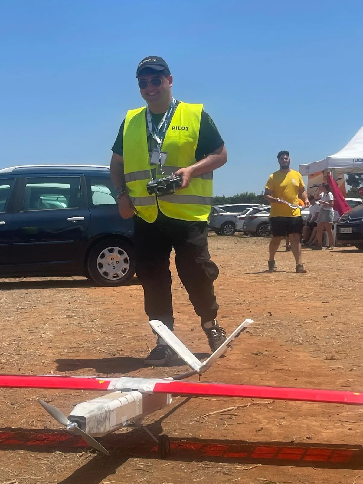
No motor at the competition. On arrival in Valencia, the team’s motors were unusable. The UVigo Aerotech team lent a new one, and with it Aurora completed the circuit and landed. Thanks to UVigo Aerotech. The lesson: critical equipment needs a chain of custody, and the motor comes first on that list.
The opaque covering. At first opaque red Oracover was used, which made it impossible to run cables through the wing or see the state of the structure. It was replaced with the transparent version.
The aerofoil deformed. The first test flight showed that the Oracover did not hold the shape of the aerofoil. Stringers were added to hold it.
The tip failed the static test. It was reinforced with a 50 cm carbon joiner running through the whole tip and part of the straight section.
In Valencia
With the new servos and the UVigo Aerotech motor, Aurora completed the circuit and landed. It finished 13th of 15, with the perseverance award and the first-landing award.